1. Introduction
A pair of motors are spinning counterclockwise , whereas the other pair are spinning clockwise ().
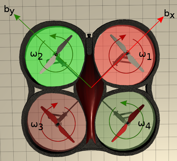
Motors on the axis rotate clockwise and on the axis axis anticlockwise: this is to negate the induced torque from the rotating blade.
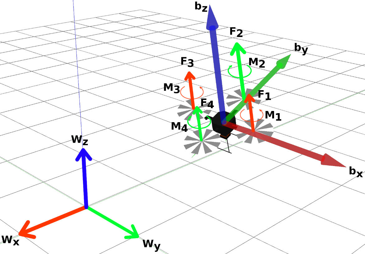
We define the thrust , and the torque moment from the propeller on .
Let’s define the roll , pitch and yawn angles as an intrinsic sequence of rotations:
Hence:
Movement along vertical direction (along $b_z$) : each motor produces a force:
where is a constant and is the angular speed. If , the quadropter will accelerate upwards.
Yaw motion (rotation about )
Magnitude of rotor torque:
The torque produces on the quadropter is opposite the direction of spin of the propeller. In order to perform a pure yawning motion, 1 pair of motors would have to increase their angular speeds by the same amount as the opposite pair would have t odecreased theirs.
By Newton’s law, the torque produce on the quadrotor is opposite to the direction of spin of the propeller: in order to have a CW rotation, torque from 2-4 must be larger than torque from 1-3
2. Kinematics and Dynamics model
Quadrator Kinematics and Dynamics Model:
is the state vector and includes 12 parameters. We define an equilibrium (hevering) state, i.e simply maintain a constant position when the quad is in the air).
- x, y, and z = the position of the quadrotor’s center of mass (CoM)
- roll (), pitch (), and yaw () Euler angles = the orientation of the body frame {B} relative to the fixed world frame {W}
- , , are the linear velocities of the quadrotor’s CoM
- , , are the angular velocities of {B} relative to {W}
For the quad to hover in place, we need:
- nominal motor thrust to hover in an equilibrium:
Using , we arrive at:
3. Cascade Controller
Although motor speed is what is directly manipulated by the onboard computer, it is actually easier to think about controlling the quadropters in terms of net thrust and movement about the roll/pitch/yaw axes.
- controller 1; mainatains quad in position
- controller 2:
In reality, most practical systems are MIMO (Multi-Input, Multi-Output). One way to handle MIMO systems is with a cascaded structure. A general form of a cascaded controller looks like this:
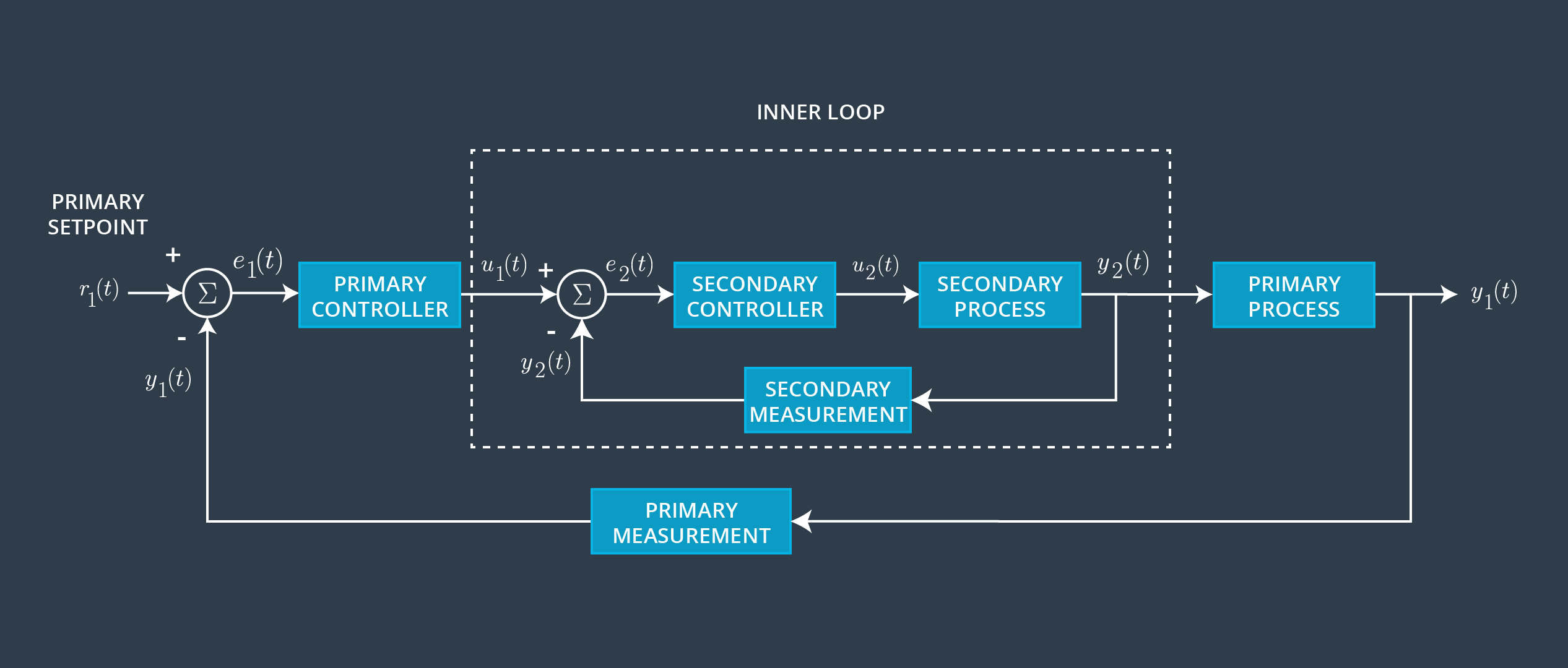
Notice that there are two closed loop feedback controllers, with the primary controller wrapping around the secondary loop. This arrangement typically requires that the inner (secondary) loop execute much faster (>10x faster) than the outer (primary) loop. In other words, if the outer loop operates at 10 Hz the inner loop needs to operate at least 100 Hz. With this difference in update frequency, the primary setpoint of the outer loop will essentially look static to the inner loop.
In the context of the quadrotor, the primary controller is responsible for maintaining its 3D position and yaw angle while the inner loop controls attitude (i.e., the roll, pitch, and yaw angles). This control scheme would allow an operator to “let go” of the control inputs and have the quadrotor maintain a steady position and orientation in 3D space (assuming external disturbances are not too great!).
Without getting too deep into the mathematics involved, let’s let r represent the vector between the quadrotor’s current 3D location and its target position. The desired linear accelerations of the quadrotor’s center of mass can be found from PID feedback of this position error. By assuming that the roll and pitch angles stay near the equilibrium hover state, it is possible to linearize the equations of motion and express the desired roll and pitch angles as a function of the desired linear accelerations. The position controller passes the desired roll, pitch, yaw angles to the attitude controller. The attitude controller returns the changes in the nominal motor speeds that would move the quadrotor towards these desired roll and pitch angles.