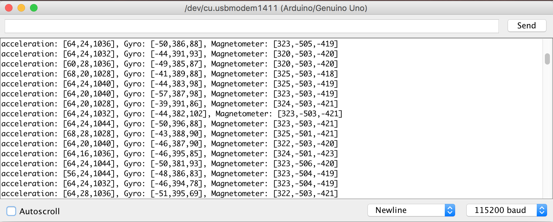
The next step in building SONIC is the installation of a Inertial Measurement Unit (IMU). The IMU will enable to determine the Roll, Pitch and Heading/Yaw angles. The details on how to calculate those angles from IMU data is the subject of another post. In this post, I focus on the installation of the IMU and on setting up the libraries and the Arduino sketch to collect the raw data.
Initial Measurement Unit
1. Gyroscope: the gyroscope measures the angular velocity (in deg/sec or revolution/sec) about the 3 axis X, Y, Z. The gyroscope has a vibrating structure to determine the rate of rotation. To keep track of the angles, we need to sum all of the rates of change over a given period of time. This is basically the integrale of the gyro data
[dessin] omega_tilt = omega + b + eta omega = true angular velocity, b=bias (temperature depednent and not static) and eta = zero mean Gaussian Noise From Gyro measurement to orientation using Taylor expansion: theta(t + delta t) ~ theta(t) + theta_dot(t) * delta_t + o(delta t^2) the last term is the approximation error theta_dot is the gyro angular velocity Pros: accurate in short term, but not reliable in long term due to drift. Bias and noise variance can be estimated, other sensor measurementsw used to correct for drift (sensor fusion) Big challenge with gyro alone: drift over time due to integration error (mostly).
2. Accelerometer: measures linear acceleration in m/s^2 or g-unit. The acceleration is differente of coordinate acceleration. The most significant of the sensed acceleration is caused by gravity. With that information, we can calculate what direction the object is facing
[dessin] The linear acceleration: a = a_g + a_i without motion: a = a_g pointing down ||a|| = 9.81 m/s2=1g With motion: a_g + a_i Pros: accurate in long term because no drift (earth gravity does not change) Problem: noisy measurement, unreliable in short run due to motion.
3. Magnetometer: it measures magnetic field strength in Gauss or Tesla. The chip is used as a digital compass to sense the angle from magnetic north (not the true north) in degrees. Use earth magnetic field in Gauss or Tesla. Actual direction depdens on lattitude longitude. Distorsion due to metal/electronics. Difficult to work with magnetometer without proper calibration Pros: magnetometer complementary of accelerometer gives heading. Cons: affected by metal,
IMU part
This IMU includes a 3 axes accelerometer, 3 axis gyroscope and 3 axis magnetometer, resulting in 9 axes of data.
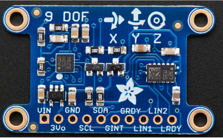
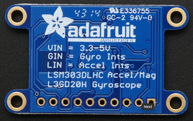
Here are the specs:
- L3GD20H 3-axis gyroscope: ±250, ±500, or ±2000 degree-per-second scale
- LSM303 3-axis compass: ±1.3 to ±8.1 gauss magnetic field scale
- LSM303 3-axis accelerometer: ±2g/±4g/±8g/±16g selectable scale
Where to place the IMU and arduino connections?
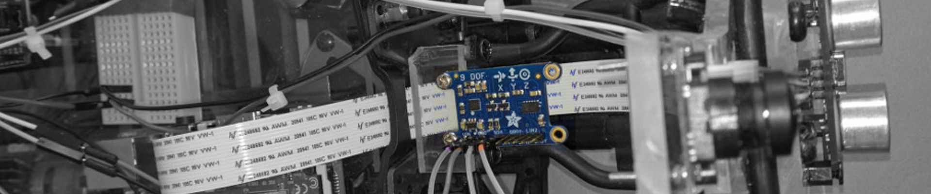
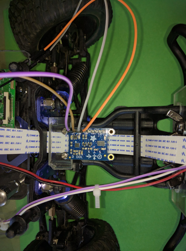
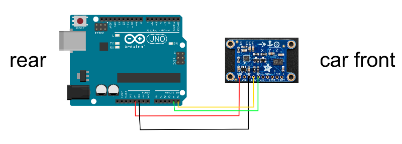
The best is to place the IMU far from any of source of magnetic field that could interfere with the Magnetometer. Magnetic material such as Iron, steel can also distort field lines. At the back of the car, we have the motor which uses a strong permanent magnet, so that’s a no-no. A good position for the IMU is at the front of the car, centered with the 2 front wheels. The signal pins to be connected are SDA and SDL which are plugged into the Analog Pin 4 (A4) and Pin 5 (A5) respectively.
 |
 |
Software
Adafruit did a good job detailing how to get started with the IMU (check out their tutorial. We need to download 4 zip files:
| Adafruit Sensor Library | Adafruit LSM303 Library | Adafruit L3GD20 Library | Adafruit 9DoF Library |
and then unzip them in the library folder of the Arduino.